
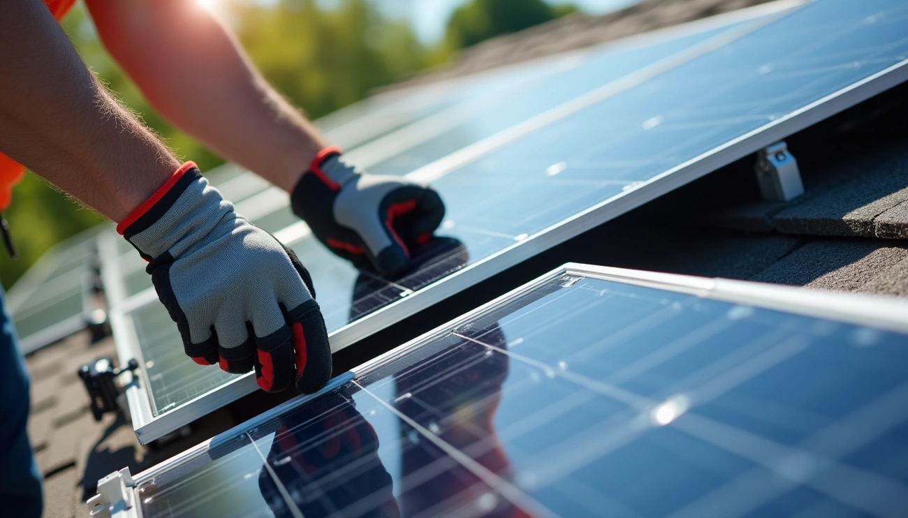
Solar panels are connected in series or parallel to control voltage and current. A series connection links positive to negative terminals to increase voltage, while a parallel connection links positive to positive and negative to negative to increase amperage. Installers connect panel strings using MC4 connectors, then route power to a combiner box, inverter, and the home’s electrical panel.
Understanding Solar Panel Wiring Basics
Before diving into solar panel wiring, you need to grasp three fundamental electrical concepts that govern how your system operates.
Key Electrical Terms You Need to Know
Voltage (V), measured in volts, represents the difference in electrical charge between two points in a circuit. This difference causes electricity to flow and indicates potential energy that can be released. In a solar array, irradiance directly impacts voltage; more sunlight produces higher voltage. Temperature also plays a role, reducing panel energy output as heat increases.
Current, represented as ‘I’ in equations and measured in amperes (amps), defines the rate at which electrical charge flows through your system. Power (P), measured in watts, calculates the rate of energy transfer using the formula P = V × I. Understanding these relationships helps you size components correctly and troubleshoot performance issues.
Components Required for Solar Panel Connections
Solar panel wiring requires specific cables and connectors designed for photovoltaic applications. PV wire or solar cable interconnects your panels during the stringing process. These cables withstand harsh outdoor conditions, including extreme temperatures and moisture.
MC4 connectors serve as the standard connection method for solar installations. Their locking mechanism prevents accidental disconnection and ensures weatherproof connections throughout your system’s lifespan. Wire management clips and zip ties secure cables and protect them from potential damage.
Circuit breakers or fuses provide overcurrent protection, with sizing dependent on your system’s components and voltage specifications. Additionally, charge controller and inverter cables connect these components to your battery bank.
Types of Wires Used in Solar Systems
PV wire differs significantly from standard electrical cables. Cross-linked polyethylene (XLPE) insulation provides superior resistance to UV exposure and moisture. Temperature ratings reach at least 90°C, with some PV cables rated for 150°C in dry conditions. This durability extends cable lifespan beyond 25 years.
Copper conductors offer better conductivity than aluminum alternatives, allowing thinner wires to carry equivalent current. Copper also resists temperature fluctuations and bending better than aluminum. In contrast, aluminum requires regular maintenance due to corrosion at connection points.
Stranded wire construction provides greater flexibility and conductivity compared to solid wire, making it the preferred choice for solar installations. The multiple metal strands create more surface area for current flow, particularly beneficial in mobile applications or installations requiring wire flexibility.
Solar Panel Wiring Methods: Series vs Parallel
Solar panel wiring follows three primary configurations, each affecting voltage and current differently. Your choice determines system performance, inverter compatibility, and how your array responds to shading.
How to Connect Solar Panels in Series
Series wiring connects the positive terminal of one panel to the negative terminal of the next panel. This creates a single pathway where voltages add together while current remains constant. For example, wiring two 18V panels in series produces 36V output, but amperage stays at 5.5A.
The process is straightforward. Connect each panel’s positive cable to the neighboring panel’s negative terminal using MC4 connectors. The female MC4 connector marks the positive cable; the male connector indicates negative. Continue this pattern until all panels link together. The first panel’s positive cable and last panel’s negative cable remain loose for connection to your inverter or charge controller.
Series connections work best for larger systems over 4 kilowatts and installations with long distances between panels and inverter. High voltage reduces power loss along cables. However, shading becomes problematic. When one panel gets shaded, the entire string’s performance drops since panels depend on each other.
How to Connect Solar Panels in Parallel
Parallel wiring joins all positive terminals together and all negative terminals together. This configuration increases current while voltage remains equal to a single panel. Four 35W panels at 21.6V and 2.13A wired in parallel produce 21.6V at 8.52A total.
Branch connectors or combiner boxes facilitate these connections. Y-branch connectors accept multiple positive inputs, combining them into one output cable. Repeat this process for negative terminals.
Parallel configurations excel in small off-grid systems like RVs and boats. Panels operate independently, so shading one panel doesn’t affect others. This tolerance makes parallel wiring suitable for partially shaded locations.
Series-Parallel Connection Configuration
Series-parallel wiring combines both methods. Create multiple series strings first, then connect those strings in parallel. For instance, wire two panels in series to achieve 43.2V at 2.13A. Build a second identical string. Connect both strings in parallel for 43.2V at 4.26A total.
This configuration balances voltage and current requirements while providing partial shade tolerance. If one panel in a series string experiences shading, only that string suffers reduced output.
Which Wiring Method Is Best for Your System
Your wiring choice depends on system size, inverter specifications, shading conditions, and cable length. Series connections suit string inverters requiring higher voltages. Parallel setups work well with microinverters and PWM charge controllers. Match your configuration to equipment specifications and site conditions for optimal performance.
Step-by-Step Guide to Connecting Solar Panels
Installing your system requires methodical execution across six critical phases. Each step builds upon the previous, creating a safe and functional solar array.
Step 1: Gather Your Equipment and Review Specifications
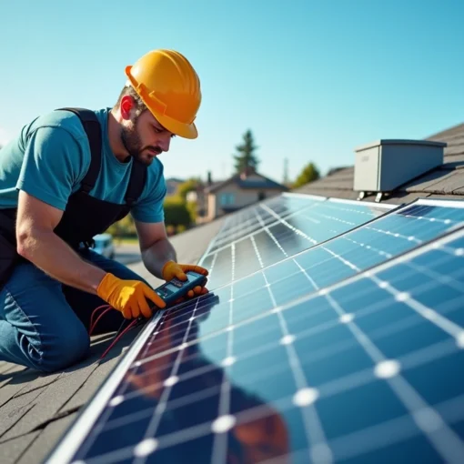
Assemble your tools before starting. You’ll need a screwdriver, electric drill, wire stripper, cable twister, multimeter, insulation tape, and crimping clamp. Wear insulation gloves and safety glasses during installation. Review your panel and inverter datasheets to understand voltage ranges, current ratings, and compatibility requirements.
Step 2: Calculate String Size and Panel Configuration
Determine how many panels fit within your inverter’s input voltage range. Web-based string sizers require site location, temperature extremes, panel specifications, and inverter model. Temperature affects voltage output significantly, requiring compensation calculations to prevent equipment damage.
Step 3: Wire Solar Panels Together Using MC4 Connectors
Strip 6-8 mm of insulation from your solar wire. Insert the exposed wire into the metal crimp terminal and crimp securely using an MC4-specific tool. Slide the crimped terminal into the connector housing until it clicks. The male connector carries negative polarity; female carries positive.
Step 4: Connect Solar Panels to the Inverter
Connect your array’s DC output cables to the inverter’s DC input terminals. Verify correct polarity and secure all connections. Confirm input voltage and current remain within inverter specifications before proceeding.
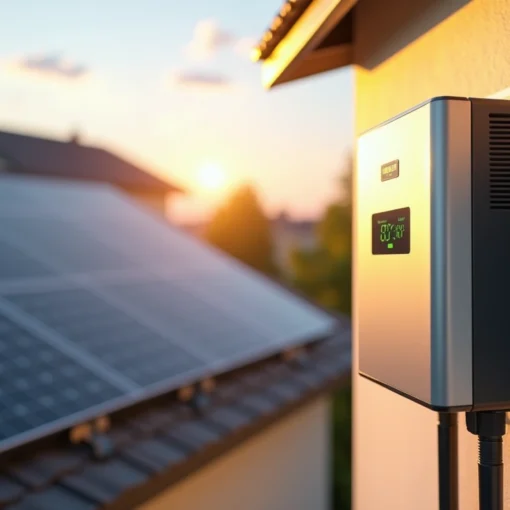
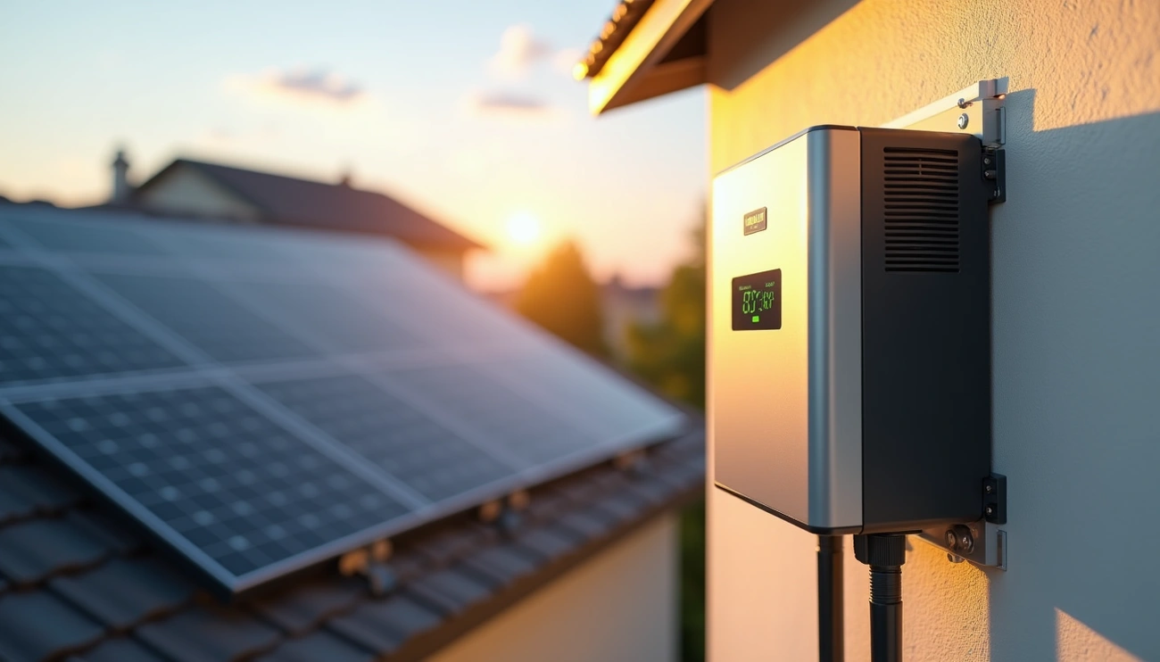
Step 5: Connect the Inverter to Your Home’s Electrical Panel
Shut off the main breaker at the panel top. Connect the black wire first, then red wire to corresponding terminals. Attach the white neutral wire to the neutral bus, then green ground wire to the ground bus.
Step 6: Install Disconnects and Ground the System
Install DC disconnects within sight of your inverter, maximum 6 feet away. Place AC disconnects near the meter for utility access. Connect the equipment grounding conductor to your main service panel’s grounding busbar. Ground resistance should measure less than 5 ohms.
Important Considerations When Wiring Solar Panels
Critical factors determine whether your solar panel wiring performs reliably over decades of operation.
Ensure Voltage Stays Within Inverter Range
Calculate maximum open circuit voltage at your site’s lowest temperature. Cold conditions increase Voc, and exceeding your inverter’s maximum DC input voltage damages equipment permanently. Specifically, when calculating panels in series, factor both Voc and temperature coefficient. An example calculation shows panels with -0.25% temperature coefficient at -10°C produce corrected Voc of 61.5V. If your inverter has 1100V maximum DC input, divide 1100V by 61.5V to determine maximum panels per string.
Account for Temperature Effects on Performance
Module temperature reduces efficiency by 0.4-0.5% per degree Celsius. Panels with lower temperature coefficients maintain better performance; N-type TOPCon panels show -0.29%/°C compared to higher coefficients in other technologies. Higher temperatures increase internal resistance and reduce voltage output.
Match String Conditions to MPPT Inputs
Balance string configurations across multiple MPPT inputs. Unequal strings connected in parallel reduce efficiency. Each MPPT input should receive strings with matching voltage characteristics. Additionally, modules with different orientations require separate MPPT channels.
Follow Local Electrical Codes and Safety Standards
NEC Article 690 establishes electrical safety requirements for PV systems. Equipment grounding of module frames and conductor enclosures is required. Work with licensed electricians familiar with NEC Article 690. Local jurisdictions may impose additional requirements beyond national codes.
Conclusion
You now have everything you need to wire your solar panel system correctly and safely. Whether you choose series, parallel, or series-parallel configuration, make sure you match your setup to your inverter specifications and local conditions.
Take your time with the installation process, double-check voltage calculations, and equally important, follow all electrical codes. With proper planning and execution, your solar array will deliver reliable performance for decades to come.

